 |
|
|
|
|
A、 军品级/工业级电子盘一
B、军工电子盘/CF卡二
C、军工电子盘/CF卡三
D、军工电子盘/CF卡四E
固态存储设备
F存储设备读写器
G存储复制工作站
H
存储设备转换器 I其它J磁盘阵列
KIDE 电子盘 L
SATA电子硬盘
MSCSI电子盘
N
PMC、cPCI、VME FFD 军品级/工业级电子盘一
B、军工电子盘/CF卡二
C、军工电子盘/CF卡三
D、军工电子盘/CF卡四E
固态存储设备
F存储设备读写器
G存储复制工作站
H
存储设备转换器 I其它J磁盘阵列
KIDE 电子盘 L
SATA电子硬盘
MSCSI电子盘
N
PMC、cPCI、VME FFD
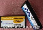 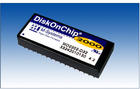  

DiskOnChip IDE Pro |
简单、可扩充、随买随用 - Simple, Scalable, Ready to Run
DiskOnChip IDE Pro
读/写速度非常快而且容易与任何系统集成,同时也提供难以置信的效能和稳定性。它提供内建Block Device 仿真,无须安装任何驱动程序。
DiskOnChip IDE Pro 简介
DiskOnChip IDE Pro 将使 DiskOnChip 的产品线变得完整, 提供完全的 IDE
储存能力及高性能。内建 ECC 系统及弹性的设计选择。它可以与任何操作系统在任何安装有 IDE bus 的系统上运作。
|

|

|
操作简单
DiskOnChip IDE pro 操作非常简单。只需要安装至 IDE插槽,选择 master 或者是
slave mode 就马上使用。无须任何驱动程序。
快捷
DiskOnChip IDE Pro 提供独特的内建 16 位快闪存取。这个功能提供比其它
IDE 储存设备都高的效能。
稳定可靠
『稳定』一向以来是 DiskOnChip 系列产品的代名词。DiskOnChip IDE Pro
延续这个优良的传统:M-Systems 将ECC 功能内建于 DiskOnChip IDE Pro,让它可以随时快速侦测及修正错误数据。每一个
DiskOnChip IDE Pro 都受严格的压力及 Power-Cycling测试,确保它们都达到M-Systems 的严格要求。
具弹性
DiskOnChip IDE Pro 提供 16MB至 256MB 的储存容量。DiskOnChip IDE
Pro提供 40-pin 及 44-pin 插槽,它可以非常容易的在任何拥有 IDE 插槽的系统平台安装。DiskOnChip IDE Pro
有一颗LED 显示运作情况,M-Systems精心设计的外壳,可用螺丝稳健的安装在任何装置上。
DiskOnChip IDE
PRO – 主要功能
| 功能 |
优点 |
完全IDE磁盘功能仿真
|
容易整合 - 只需将DiskOnChip IDE Pro
安装到插槽上即可以使用。
|
独特内建16位快闪存取
|
高效能 – 非常快速的读写率,完全仿真硬盘运作。
|
多种容量选择 -
16MB-256MB
|
可扩充Scalable – 提供简单方便的升级方法及设计。
|
内建 ECC。所有产品均经过M-Systems
压力及power-cycling 测试。
|
非常稳定可靠 –
每512bytes可自动侦测2bite错误数据及修改1bite数据。
|
所有驱动程序都于 BIOS 处理
|
无须驱动程序 – 兼容于任何操作系统
|
40-pin &
44-pin插槽,外壳以人工学精心设计。
|
多种外型设计 - DiskOnChip IDE Pro
绝对可以安装在任何使用 IDE 的装置上。 |
支持 PIO 0-4.
Master/Slave mode 使用开关控制。
|
支持所有 IDE Modes – 无论是新或旧的平台。每个
bus 支持2个装置联机。 |
|
| |
Pin 列表及描述
|
| |
|
Pin 列表 |
| Pin
号码 |
讯号 |
功能 |
| 1 |
RESET# |
Host reset |
| 3 |
HD7 |
Data bit 7 |
| 5 |
HD6 |
Data bit 6 |
| 7 |
HD5 |
Data bit 5 |
| 9 |
HD4 |
Data bit 4 |
| 11 |
HD3 |
Data bit 3 |
| 13 |
HD2 |
Data bit 1 |
| 15 |
HD1 |
Data bit 1 |
| 17 |
HD0 |
Data bit 0 |
| 19 |
GND |
Ground
|
| 21 |
NC |
Not
connected |
| 23 |
DIOW# |
Host I/O
Write |
| 25 |
DIOR# |
Host I/O
Read |
| 27 |
IORDY |
I/O Ready |
| 29 |
NC |
Not
connected |
| 31 |
INTRQ |
Interrupt
Request |
| 33 |
HA1 |
Host Address
Bus bit 1 |
| 35 |
HA0 |
Host address
Bus bit 0 |
| 37 |
CS0# |
Chip Select
0 |
| 39 |
DASP# |
Drive
Active/Drive 1 present |
| 412 |
VCC |
Supply
Voltage |
| 432 |
GND |
Ground |
|
|
|
|
Pin 描述 |
| Pin
号码 |
输入类别 |
功能 |
|
2 |
GND |
Ground |
|
4 |
HD8 |
Data bit 8 |
|
6 |
HD9 |
Data bit 9 |
|
8 |
HD10 |
Data bit 10 |
|
10 |
HD11 |
Data bit 11 |
|
12 |
HD12 |
Data bit 12 |
|
14 |
HD13 |
Data bit 13 |
|
16 |
HD14 |
Data bit 14 |
|
18 |
HD15 |
Data bit 15 |
|
20 |
40-pin | VCC1
44-pin | Key |
Supply Voltage
Cut pin |
|
22 |
GND |
Ground |
|
24 |
GND |
Ground |
|
26 |
GND |
Ground |
|
28 |
CSEL |
Master/Slave |
|
30 |
GND |
Ground |
|
32 |
IOIS16# |
CS I/O 16 bit
|
|
34 |
PDIAG# |
Passed diagnostics |
|
36 |
HA2 |
Host Address Bus bit 2 |
|
38 |
CS1# |
Chip Select 1 |
|
40 |
GND |
Ground
|
|
422 |
VCC |
Supply Voltage |
|
442 |
RESERVED |
Reserved |
|
|
| |
|
1. |
In the 40-pin
version, this pin is defined as VCC to reduce the need for an
external power connector. In the 44-pin version, this pin is defined
as KEY, according to the ATA standard. |
|
| |
| 2. |
DiskOnChip IDE Pro 40-pin
version does not contain pins 41-44 |
|
| |
NC = These pins are not
connected internally. This is for pin 21, 29. |
| |
RESERVED = All reserved
signals must be left floating. |
Pin 描述列表
|
|
讯号 |
Pin 号码 |
描述 |
讯号类别 |
|
RESET# |
1 |
Host reset:
Active low. |
Input |
| HD15-HD0 |
3-18 |
Host Data bus
[15:0]. 16-bit bi-directional data input/output bus. HD15 is the
most significant bit, while HD0 is the least significant bit.
This bus carries data, commands and status information between
the host and DiskOnChip IDE Pro. The lower 8 bits are used for
8-bit register transfers. Data transfers are 16-bits wide. |
I/O |
| DIOW# |
23 |
Device I/O
Write: Active low. Gates the data from the bus into DiskOnChip
IDE Pro. The clocking occurs on the rising edge of the signal.
|
Input |
| DIOR# |
25 |
Device I/O
Read: Active low. Gates the data onto the bus from DiskOnChip
IDE Pro. The clocking occurs on the falling edge of the signal.
|
Input |
| IORDY |
27 |
II/O Ready:
Negated by DiskOnChip IDE Pro to extend the host transfer cycle
(Read or Write) when the device is not ready to respond to a
data transfer request. |
Output |
| CSEL |
28 |
Configuration
Select: Determines the device configuration as either Master or
Slave. If CSEL is negated, then the device address is Master; if
CSEL is asserted, then the device address is Slave. |
Input |
| INTRQ |
31 |
Interrupt
Request: Interrupt request from DiskOnChip IDE Pro to the host.
The output of this signal is tri-stated if the host disables the
interrupt. When asserted, this signal is negated by the device
within 400 nsec of the negation of DIOR# that reads the Status
register. When asserted, this signal is negated by the device
within 400 nsec of the negation of DIOW# that writes the Command
register. |
Output |
| IOIS16# |
32 |
I/O IS I6-Bit:
Active low. Asserted (low) by DiskOnChip IDE Pro to indicate to
the host that the current cycle is a 16-bit (word) data
transfer. When the signal is negated (high), an 8-bit data
transfer is performed. |
Output |
| HA2-HA0 |
33,35,36 |
Host Address
bus HA[2:0]: Select the registers in the DiskOnChip IDE Pro
controller. |
Input |
| PDIAG# |
34 |
Passed
Diagnostics: Active low. Informs the Master drive that the
self-diagnostic of the Slave drive has ended. |
I/O |
| CS0# |
37 |
Host Chip
Select 0: Active low. Selects the Command Block Registers. |
Input |
| CS1# |
38 |
Host Chip
Select 1: Active low. Selects the Command Block Registers. |
Input |
| DASP# |
39 |
Drive
Active/Drive1 Present: Active low. This is a time-multiplexed
signal that indicates that a device is active, or that Device 1
is present. |
I/O |
| GND |
2,19,22,24,26,30,40,43 |
Ground |
Ground |
| VCC |
41, 42 |
Power supply |
Supply |
|
|
Ordering Information
|
Ordering
Information |
Total
Capacity |
IDE Connector
(No. of pins) |
Mechanical
Alignment |
Internal Bus
Width |
| MD1050-D16 |
16MB |
40-pin |
Vertical |
8-bit |
| MD1050-D32 |
32MB |
40-pin |
Vertical |
16-bit |
| MD1050-D64 |
64MB |
40-pin |
Vertical |
16-bit |
| MD1050-D128 |
128MB |
40-pin |
Vertical |
16-bit |
| MD1050-D256 |
256MB |
40-pin |
Vertical |
16-bit |
|
| MD1051-D16 |
16MB |
44-pin |
Vertical |
8-bit |
| MD1051-D32 |
32MB |
44-pin |
Vertical |
16-bit |
| MD1051-D64 |
64MB |
44-pin |
Vertical |
16-bit |
| MD1051-D128 |
128MB |
44-pin |
Vertical |
16-bit |
| MD1051-D256 |
256MB |
44-pin |
Vertical |
16-bit |
|
|
|

